シリーズ
C2.954-1
シーケンスバルブ、呼び径4

ラインアップ情報
説明
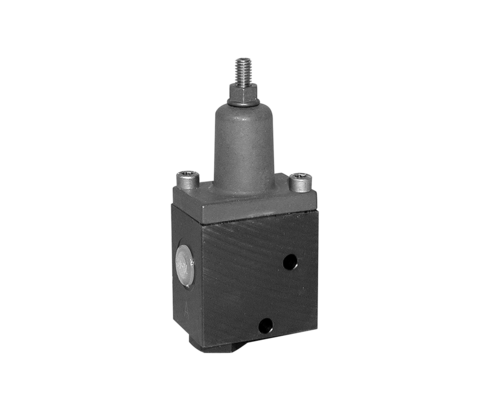
C 2.954 シーケンスバルブ ND 4
シーケンスバルブは、圧力によるシーケンス制御を必要とするワーククランプ回路に使用されます。コンパクトなサイズのため、クランプ治具に直接取り付けることが可能で、単動式シリンダーの場合、パワーユニットから治具への圧力ラインは1本のみで済みます。


製品 (6)
読み込み中…
| アイテム番号 | CADデータ | Typ | Ausführung | max. Betriebsdruck [bar] | Bauart | |
|---|---|---|---|---|---|---|
|
アイテム番号
|
CADデータ
|
プロパティ
| ||||
|
アイテム番号
|
CADデータ
|
プロパティ
| ||||
|
アイテム番号
|
CADデータ
|
プロパティ
| ||||
|
アイテム番号
|
CADデータ
|
プロパティ
| ||||
|
アイテム番号
|
CADデータ
|
プロパティ
| ||||
|
アイテム番号
|
CADデータ
|
プロパティ
|
読み込み中…
アイテム番号
Typ
Zuschaltventil
Ausführung
Rohrgewindeausführung
max. Betriebsdruck [bar]
500
Bauart
Schieberventil
max. Volumenstrom [l/min]
8
Anschlussgröße
G1/4
Steuerung
druckabhängig
Einstellbereich
10 – 75 bar
アイテム番号
Typ
Zuschaltventil
Ausführung
Flanschausführung
max. Betriebsdruck [bar]
500
Bauart
Schieberventil
max. Volumenstrom [l/min]
8
Anschlussgröße
Ø 5 mm
Steuerung
druckabhängig
Einstellbereich
10 – 75 bar
アイテム番号
Typ
Zuschaltventil
Ausführung
Rohrgewindeausführung
max. Betriebsdruck [bar]
500
Bauart
Schieberventil
max. Volumenstrom [l/min]
8
Anschlussgröße
G1/4
Steuerung
druckabhängig
Einstellbereich
10 – 150 bar
アイテム番号
Typ
Zuschaltventil
Ausführung
Flanschausführung
max. Betriebsdruck [bar]
500
Bauart
Schieberventil
max. Volumenstrom [l/min]
8
Anschlussgröße
Ø 5 mm
Steuerung
druckabhängig
Einstellbereich
10 – 150 bar
アイテム番号
Typ
Zuschaltventil
Ausführung
Rohrgewindeausführung
max. Betriebsdruck [bar]
500
Bauart
Schieberventil
max. Volumenstrom [l/min]
8
Anschlussgröße
G1/4
Steuerung
druckabhängig
Einstellbereich
100 – 450 bar
アイテム番号
Typ
Zuschaltventil
Ausführung
Flanschausführung
max. Betriebsdruck [bar]
250
Bauart
Schieberventil
max. Volumenstrom [l/min]
8
Anschlussgröße
Ø 5 mm
Steuerung
druckabhängig
Einstellbereich
100 – 450 bar
アクセサリー (1)
| アイテム番号 | CADデータ | 商品の説明 |
|---|---|---|
|
アイテム番号
|
CADデータ
|
商品の説明
O-ring 7 x 1.5 mm, NBR
as per data sheet B1.5091
|
読み込み中…
アプリケーション例
アプリケーション例1
ワークは、油圧式クランプシリンダーを使用して治具に位置決め、クランプされます。
クランプシーケンス
- シリンダー1がワークをストッパーaに押し付けます。
- 圧力が高まり30barに達すると、シーケンスバルブが開きます。
- シリンダー2と3が伸長し、ワークをストッパーbとcに押し付けます。
- シーケンスバルブの開いた状態により、すべてのシリンダーで油圧が均一に上昇します。
アプリケーション例2
5つの単動式クランプシリンダーのシーケンス制御。
登録
初めてご利用ですか?
ログインエリアの無料特典をご利用ください:
- CADデータのダウンロード
- 取扱説明書をダウンロードする
ログイン
お帰りなさい
お帰りなさい!すでに登録済みのユーザーアカウントにログインしてください
読み込み中…
CADデータの読み込みに中にエラーが発生しました。インターネット接続を確認し、再度お試しください
ご注意:当社のCADデータは簡略化されたデータで、製品の外形と接続部分を表示しています(利用規約もご参照ください)。許容誤差を含む正確な寸法については、特に取付け穴や特殊クランプなどの取付け具に関する情報については、必ず該当するカタログシートをご参照ください。'
読み込み中…
予期せぬエラーが発生しました。ページを再読み込みするか、後で再度お試しください