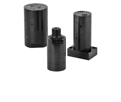
油圧ブースター、0.2 – 2.6 l/min

説明
増圧器内に、油圧式バルブによりストロークエンドで自動的に反転する振動式ポンプが設置されています。ピストン面積の比率は増圧倍率に対応しています。
低圧域でのスムーズな流量を確保するため、バイパスラインによりポンプがバイパスされます。パイロット式チェックバルブが高圧を遮断します。
機能
入力INからチェックバルブRV1、RV2、DVを介して圧力なしで作動油が出力Hに供給され、これにより油圧シリンダーに流れ込みます。逆圧力が上昇すると、振動ポンプOPが動作を開始します。出力Hの流量は次第に減少し、最大作動圧に達するとほぼゼロになります。
INに低圧が供給されている限り、ポンプはHの圧力を一定に保持します。INとRのポート間は、機能上の理由からポンプを漏れなく密封できないため、約50 cm³/分の漏れが発生します。
シリンダーを後退させるには、ポートINを減圧し、ポートRを加圧します。同時に、チェックバルブDVが開き、自由な戻り流量を可能にします。
単動式シリンダー
単動式シリンダーのみが接続されている場合、パイロット式チェックバルブの解除を制御するために、複動式バルブ機能が必要です(油圧回路図参照)。
重要な注意事項!
増圧器は極めて高い油圧を発生させます。システムは、過圧防止のための有効なレリーフバルブを必ず設置する必要があります。
増圧器の接続は必ず複動式でなければなりません。油供給のため、ポートRは減圧状態に保つ必要があります。ポンプとバルブスライドには最小クリアランスが確保されています。機能を保護するため、増圧器の入力INに高圧フィルターを必ず設置する必要があります(油圧回路図参照)。
INに圧力がある限り、増圧器はポートINとRの間で内部漏れが発生します。INに圧力がない場合、漏れが発生すると高圧領域の圧力が低下する可能性があります。
ポートHにパイロット式チェックバルブを装着することで、圧力低下を防止できます(油圧回路図参照)。これは特に非接続システム(クランプパレット)に適用されます。
| アイテム番号 | CADデータ | Typ | Ausführung | Funktionsweise | hydraulischer Anschluss | |
|---|---|---|---|---|---|---|
|
アイテム番号
|
CADデータ
|
プロパティ
| ||||
|
アイテム番号
|
CADデータ
|
プロパティ
| ||||
|
アイテム番号
|
CADデータ
|
プロパティ
| ||||
|
アイテム番号
|
CADデータ
|
プロパティ
| ||||
|
アイテム番号
|
CADデータ
|
プロパティ
| ||||
|
アイテム番号
|
CADデータ
|
プロパティ
| ||||
|
アイテム番号
|
CADデータ
|
プロパティ
| ||||
|
アイテム番号
|
CADデータ
|
プロパティ
| ||||
|
アイテム番号
|
CADデータ
|
プロパティ
| ||||
|
アイテム番号
|
CADデータ
|
プロパティ
|
ログインエリアの無料特典をご利用ください:
- CADデータのダウンロード
- 取扱説明書をダウンロードする
お帰りなさい!すでに登録済みのユーザーアカウントにログインしてください