油圧式シリンダー
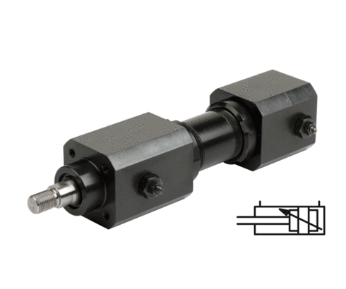
DIN ISO 6020に準拠した接続が可能な複動式油圧シリンダー。唯一の例外は全長が短い点です。ご要望に応じて、DIN ISO 60 20に準拠した長いバージョンもご用意可能です。ピストンロッド先端はねじ部となっています。固定用に、本体前部と後部に各4つのねじ穴が設けられています。
調整可能なストロークエンドクッションは、以下のアプリケーションにおいてピストンが強くあたって停止するのを防ぎます:
1. 高いピストン速度
2. ピストンロッドへの追加荷重
3. 追加荷重を相殺するための停止装置を設置できない場合
| アイテム番号 | CADデータ | Hub [mm] | Funktionsweise | Endlagenkontrolle | Endlagendämpfung | |
|---|---|---|---|---|---|---|
|
アイテム番号
|
CADデータ
|
プロパティ
| ||||
|
アイテム番号
|
CADデータ
|
プロパティ
| ||||
|
アイテム番号
|
CADデータ
|
プロパティ
| ||||
|
アイテム番号
|
CADデータ
|
プロパティ
| ||||
|
アイテム番号
|
CADデータ
|
プロパティ
| ||||
|
アイテム番号
|
CADデータ
|
プロパティ
| ||||
|
アイテム番号
|
CADデータ
|
プロパティ
| ||||
|
アイテム番号
|
CADデータ
|
プロパティ
| ||||
|
アイテム番号
|
CADデータ
|
プロパティ
| ||||
|
アイテム番号
|
CADデータ
|
プロパティ
|
| アイテム番号 | CADデータ | 商品の説明 |
|---|---|---|
|
アイテム番号
|
CADデータ
|
商品の説明
Bearing block for 1297-1X-XXXX
bearing Ø 32 H7 mm
as per data sheet G3.810
|
|
アイテム番号
|
CADデータ
|
商品の説明
Bearing block for 1298-1X-XXXX
bearing Ø 40 H7 mm
as per data sheet G3.810
|
|
アイテム番号
|
CADデータ
|
商品の説明
Rod end bearing M14 x 1.5 mm
bearing Ø 16 H7 mm
as per data sheet G3.810
|
|
アイテム番号
|
CADデータ
|
商品の説明
Rod end bearing M20 x 1.5 mm
bearing Ø 25 H7 mm
as per data sheet G3.810
|
|
アイテム番号
|
CADデータ
|
商品の説明
Rod end bearing M16 x 1.5 mm
bearing Ø 20 H7 mm
as per data sheet G3.810
|
|
アイテム番号
|
CADデータ
|
商品の説明
Rod end bearing M27 x 2 mm
bearing Ø 32 H7 mm
as per data sheet G3.810
|
|
アイテム番号
|
CADデータ
|
商品の説明
Rod end bearing M12 x 1.25 mm
bearing Ø 12 H7 mm
as per data sheet G3.810
|
|
アイテム番号
|
CADデータ
|
商品の説明
Rod end bearing M33 x 2 mm
bearing Ø 40 H7 mm
as per data sheet G3.810
|
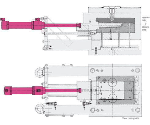
射出成形金型
サイクル ( 簡略図で示します )
1. 金型が閉まり、射出が行われる
2. ギアラックが後退し、スピンドルが外側に移動する
3. リミットスイッチが「金型を開く」信号を出す
4. 金型が開く
5. 製品が排出される
6. 金型が閉じる
7.ギアラックが前進し、スピンドルが移動する
8. リミットスイッチが「射出材料注入」の信号を発する
9. 射出材料が注入される
1. 新しいサイクル
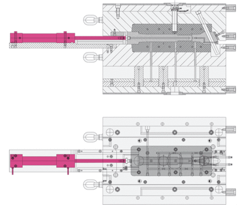
射出成形
サイクル ( 簡略図で示します )
1. 金型が閉まり、射出が行われる
2. 金型が開く
3. 油圧ブロックシリンダーがコアを金型から引き出す
4. リミットスイッチが「エジェクターシステム前進」の信号を送信
5. エジェクターシステム前進
6. ワークが落下
7. エジェクターシステム後退
8. リミットスイッチが「コア挿入」の信号を送信
9. 油圧ブロックシリンダーがコアを金型内に押し込む
10. リミットスイッチが「金型を閉じる」信号を出します
11. 金型が閉じます
12. 材料が注入されます
1. 新しいサイクル
ログインエリアの無料特典をご利用ください:
- CADデータのダウンロード
- 取扱説明書をダウンロードする
お帰りなさい!すでに登録済みのユーザーアカウントにログインしてください


